 Volmer Jensen VJ-21
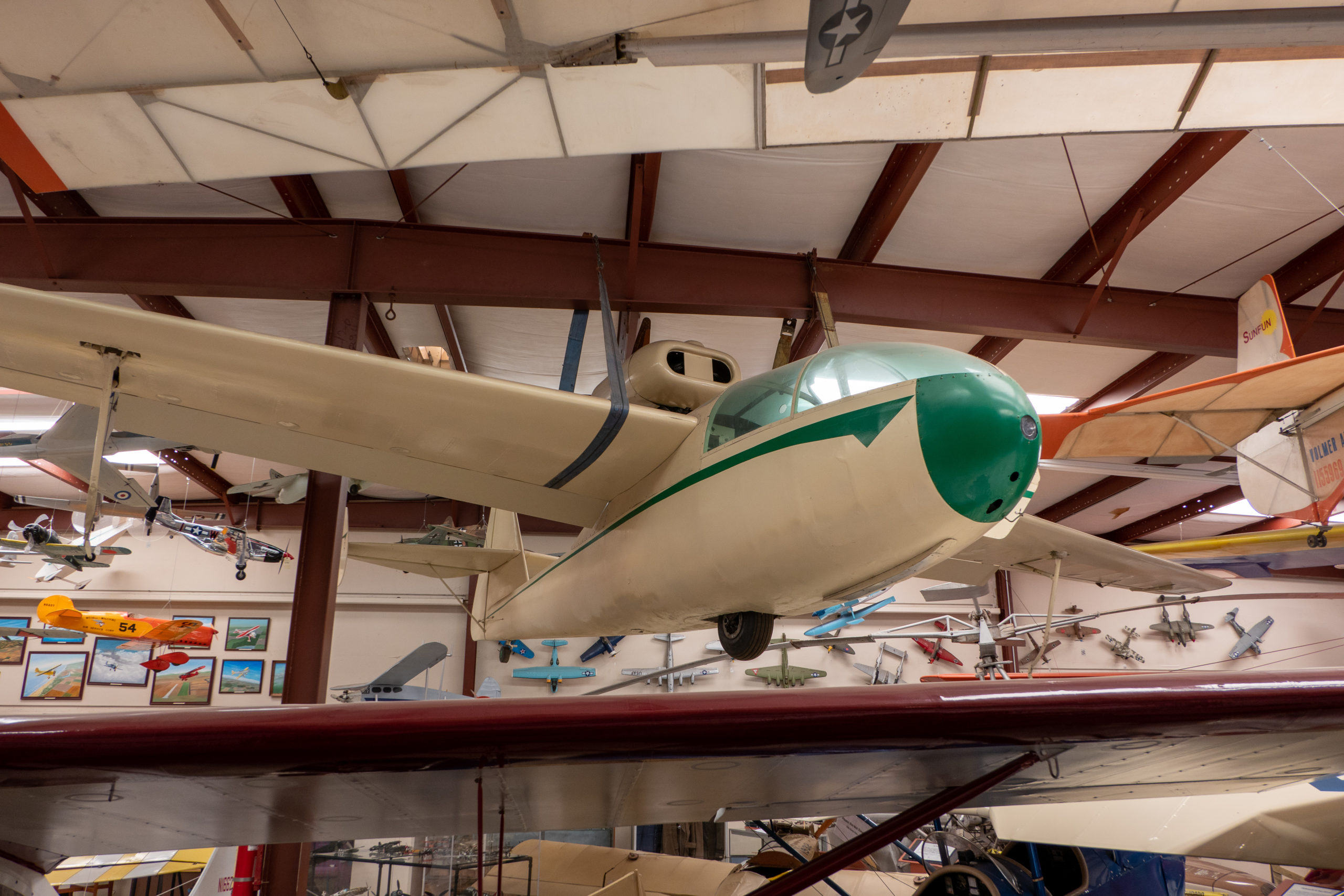
This powered glider aircraft was designed by John Carssow and Volmer Jensen, with Carssow as an expert in flight instruments responsible for the design of the cockpit, while Jensen designed wings and fuselage.
The VJ-21 was made of wood that was clad with canvas. The wing was high-winged in a self-supporting construction. Right across the central part of the wing, six struts were attached that held up the engine gondola. As a power source, a Continental engine was chosen that powered a two-blade shooting propeller. The landing gear was fixed with a wheel half recessed into the fuselage at the front of the wing. The aircraft received a lot of attention when pilot Jean Reimer completed a round-trip flight from Van Nuys California to Florida in the summer of 1947. The flight was carried out in one month.
After the prototype aircraft was piloted, production was supposed to take place at Jarvis Manufacturing in Glendale. But the production model would be made of metal and be approved for advanced flight. Due to a lack of funding, the project was cancelled. The only manufactured VJ-21 is on display here at the Wings of History Museum..
Tractor & Pusher Airplanes
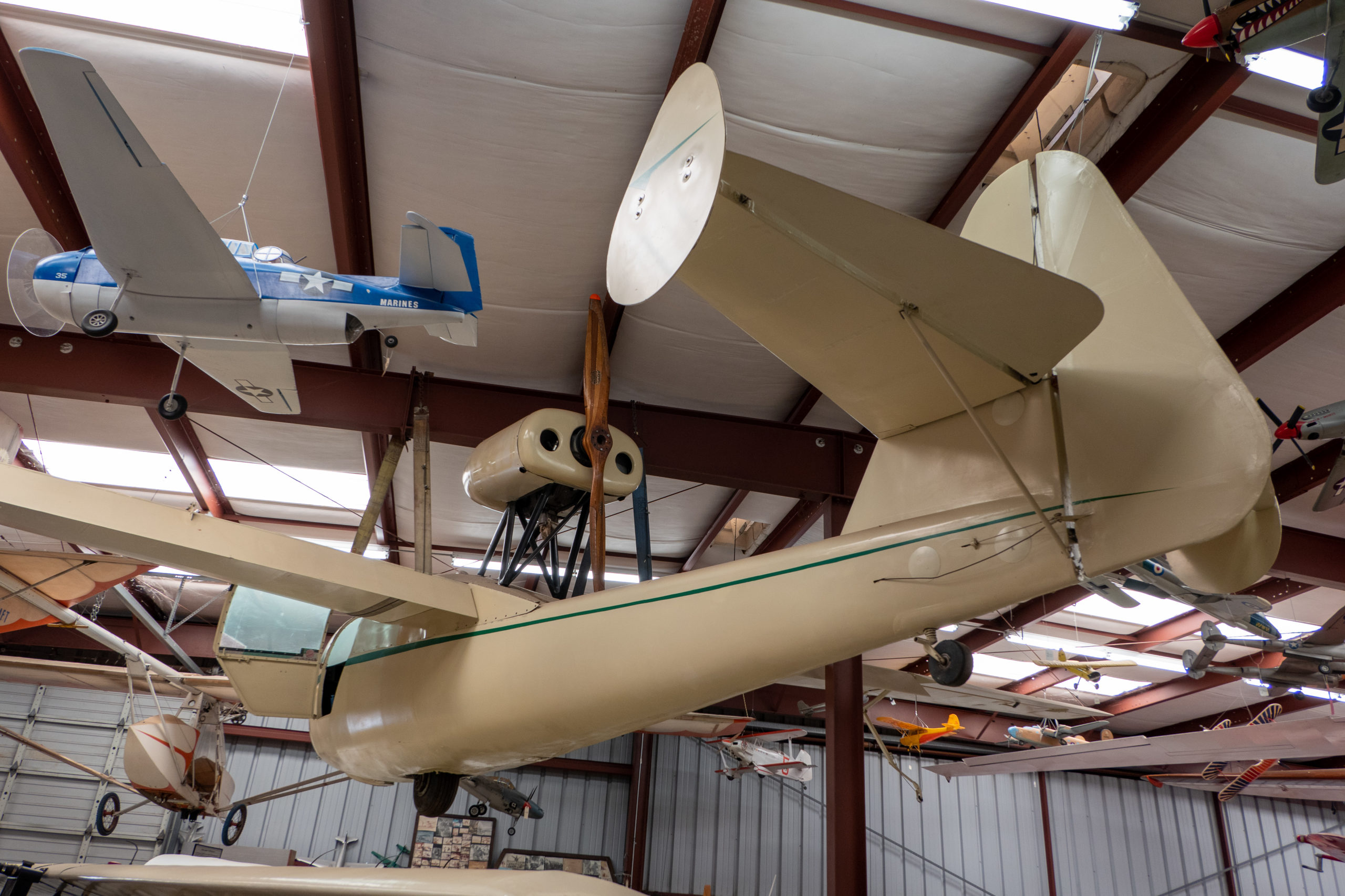
As you look at the VJ-21 hanging in the museum you may have noticed that the placement of the engine on the aircraft is a bit different than most airplanes that are here in the museum. This engine installation and location is known as a “pusher” airplane.
The other engine installation that is common on aircraft is known as a “tractor” type.
Depending upon specific design, a tractor type can deliver about 92% of the engine power into usable thrust for the airplane. A pusher is somewhat affected by the airflow being disturbed by the parts of the airplane forward of the engine/propeller installation which decreases its efficiency to about 87%. Both types of installations offer some positive and some negative attributes about the particular choice of installation.
Many early aircraft were “pushers,” such as the Wright Flyer and the Santos-Dumont 14 bis. A number of military pilot fatalities in the early years involved pusher type aircraft resulting in them being looked upon as inferior to the tractor type. Pushers were an advantage for forward-firing guns as there was no obstruction from the arc of the propeller. Additionally, if a pilot had to parachute out of a pusher there was the possibility of passing through the propeller arc.
Some advantages of tractor type installations:
- In a crash, the tractor engine can absorb much of the impact.
- Tends to reduce propeller damage from debris thrown up by aircraft wheels.
- Lower propeller noise due to the airflow contacting the propeller being undisturbed.
Some disadvantages of tractor type installations:
- The propeller accelerates air rearward which strikes the surface of the airplane resulting in what is called “scrubbing drag.”
- For small single-engine aircraft greater than 50% of the aircraft surface behind the propeller experiences this type of drag.
Some advantages of pusher type installations:
- Enhanced wing efficiency because the airflow over the wing is not disturbed by the propeller.
- Superior visibility out the front of the aircraft. The cockpit is placed well forward of the wing for weight and balance purposes resulting in improved visibility.
- Improved slow speed control as the prop blast is closer to the tail surfaces.
- A pusher needs less stabilizing vertical tail area and therefore presents less weathervane effect. The aircraft would generally be less sensitive to crosswind on takeoff.
Some disadvantages for pusher type installations:
- Power-plant cooling design is more complex than for tractor configurations where the propeller forces air over the engine.
- Due to the center of gravity often being further back on the longitudinal axis than on most tractor airplanes, pushers can be more prone to flat spins, especially if loaded improperly.
- The propeller passes through the fuselage wake, wing and other flight surface down-washes reducing propeller efficiency (some 2 to 5% less than tractor types).
- Pusher props are noisy, especially if the engine exhaust flows through the prop.
- There is a possibility of the engine momentum causing the engine to enter the aircraft cabin during a crash.
- Pusher props will tend to pick up material that is thrown into the air by the main landing gear.
- Pushers tend to have longer instrumentation and control runs back through the cabin to reach the engine.
Balancing of Flight Controls
As you look up under the left wing of the VJ-21 that is hanging in the museum you will notice a strange device that is present near the left wing aileron.
The item appears to be a bar that is attached to the lower surface of the aileron that extends forward and has a large weight bolted to the end of the bar. When the ailerons are in the neutral position this mechanism would be flush with the lower surface of the wing thereby not offering any resistance (drag) to the flow of air. This device can be used to serve two functions in the flight control system. Since the weight that protrudes forward is in front of the hinge line of the aileron it can be used for relieving some of the “heaviness” or slow response to aileron inputs by the pilot. This gives the aileron control system a measure of static balance making it easier to move in flight.
A second reason such devices are used is to prevent what is called “aileron flutter” in flight. If an aileron design is subject to “flutter” this transmits a vibration into the wing structure which can result in failure or fatigue in the structure. Flutter is not a good thing and designers often use such devices to prevent flutter from occurring. This scheme of design is also known as “static balancing” and “mass balancing” of the flight controls.
There is a second method of balancing flight control systems. That approach is referred to as “aerodynamic balancing.” It is achieved by placing a portion of the flight control surface forward of the control surface hinge line as shown in the illustration.